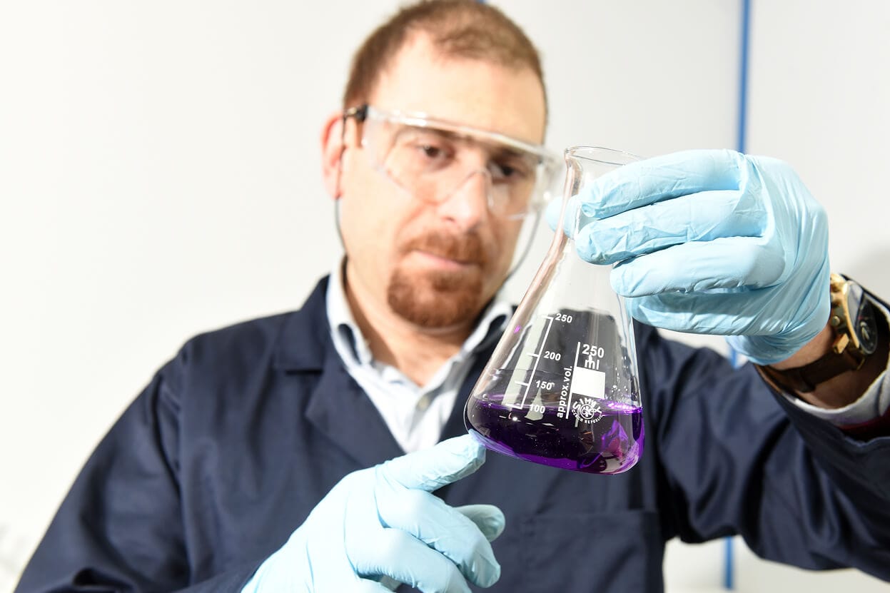

Advanced Chemical Etching (ACE), has developed a new and highly efficient chemical etching method that can improve the quality and dimensional tolerance accuracy of aluminium component manufacture to a new high.
The combination of photoresist technology and chemical reaction explains the name given to this process – photochemical etching. The steps involved in this process are described individually in the following sections.

1.1. Metal Preparation
The metal type and thickness are chosen by the customer based on the application of the finished product. A wide range of metal alloys can be processed by photochemical etching, such as stainless steel, copper, aluminium and titanium alloys. However, certain alloys are designed to have superior corrosion resistance properties and are therefore challenging to etch. Examples include nickel superalloys such as Inconel 625, although some nickel superalloys are etchable (e.g. Inconel 600).
The raw metal is prepared by cutting it into the required sheet size and then cleaning the surface. A clean metal surface is critical as contamination could potentially lead to problems during the subsequent steps of lamination and etching. The cleaning process removes grease, particulate matter and any other contaminants from the surface of the metal. Cleaning is achieved using chemical reagents (degreasing and dilute acid solutions), as well as by mechanically brushing the surface in an automatic brushing machine.
1.2. Photo-Tool Production
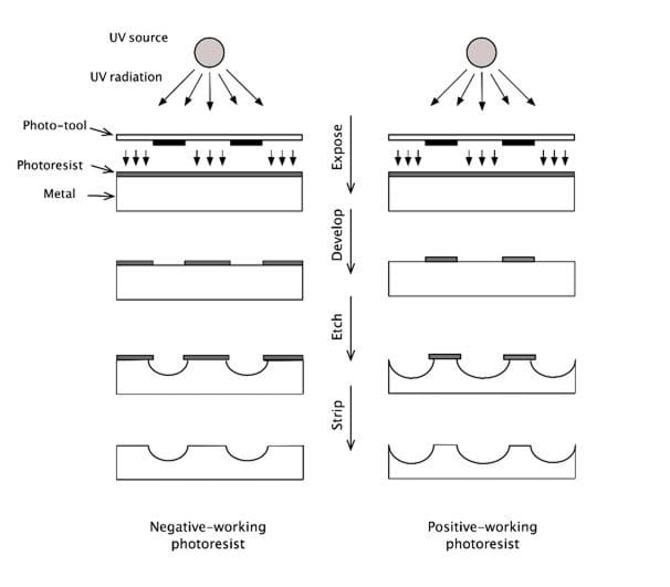
The image to be etched on the metal is produced as a digital drawing file using CAD software and is then printed on a transparent polymeric film known as the photo-tool. The image is drawn based on the dimensions specified by the customer. However, an etching phenomenon known as ‘undercut’ must also be taken into account when designing the photo-tool.
Undercut is defined as etching that takes place under the edge of the photoresist, and is caused by the fact that, when the metal is exposed to the etching solution, etching takes place in all directions (this is termed isotropic etching). This means that the etchant attacks the metal both vertically (the desired direction) and horizontally, causing the metal under the edge of the photoresist to be etched as can be seen in the figure above. As a result, the size of the etched feature produced is larger than the size defined by the printed image. This effect must be factored in when designing the digital drawing by including an etch allowance or compensation. The compensation is calculated based mainly on the required depth of the etched feature. The deeper the etched feature, the larger the undercut and the bigger the compensation required to produce the correct dimension.
1.3. Lamination
In this step, the metal sheet is coated with a suitable dry film photoresist. This is done by sandwiching the metal sheet between two layers of photoresist while applying pressure and heat during the coating process in order to achieve a good adhesion between the photoresist and the metal surface.
The photoresist is a polymeric layer containing photo-sensitive monomers as well as photo-initiators. Upon exposure to UV light in the next step, the monomers within the photoresist react to form a hard polymer (only in the areas exposed to the UV light). The hardened polymer is used to selectively protect the surface of the metal from the action of the etching reagent. It is therefore important to ensure that the photoresist is able to withstand the chemical reagents used downstream in the etching step. If the photoresist becomes weakened by exposure to the etching solution, it will lose its protective function and will cause the underlying metal to be etched. Photoresist detachment results in a defective product.
1.4. Printing And Exposure
Here, the image from the photo-tool is transferred onto the photoresist-coated (i.e. laminated) metal sheet. This step specifies the exact areas where the photoresist must be dissolved or removed in order to allow the metal in these areas to be etched.
It should be noted that there are two types of photoresists. If the opaque lines on the photo-tool correspond to the areas that need to be etched, the photoresist is described as a negative-working photoresist. On the other hand, if the opaque lines specify the areas that need to be protected, we have a positive-working photoresist. This is illustrated in the figure above.
In the process described here, a negative-working photoresist is assumed. First, the photo-tool is carefully aligned on top of the laminated metal sheet. The three-layered assembly (photo-tool, photoresist and metal) is then exposed to UV radiation from a UV lamp. Under the influence of UV radiation, photo-initiators within the photoresist initiate a reaction that converts the acrylate monomers into a polymer. The areas of the photoresist that are protected from the radiation by the opaque lines of the photo-tool remain unaffected (i.e. remain ‘soft’ or soluble), while the areas exposed to the radiation through the transparent areas of the photo-tool undergo a polymerisation reaction that causes the photoresist in these areas to harden and become insoluble.
1.5. Developing
The ‘soft’ or non-polymerised areas of the photoresist are removed by washing the laminated sheet with a mild alkaline solution. On the other hand, the polymerised (hardened) areas of the photoresist remain unaffected by this step.
As a result, there are now two different areas on the surface of the metal: (i) a bare or exposed area formed by selectively dissolving the ‘soft’ photoresist to produce the desired pattern, and (ii) a protected area covered by the hardened or polymerised photoresist.
1.6. Etching
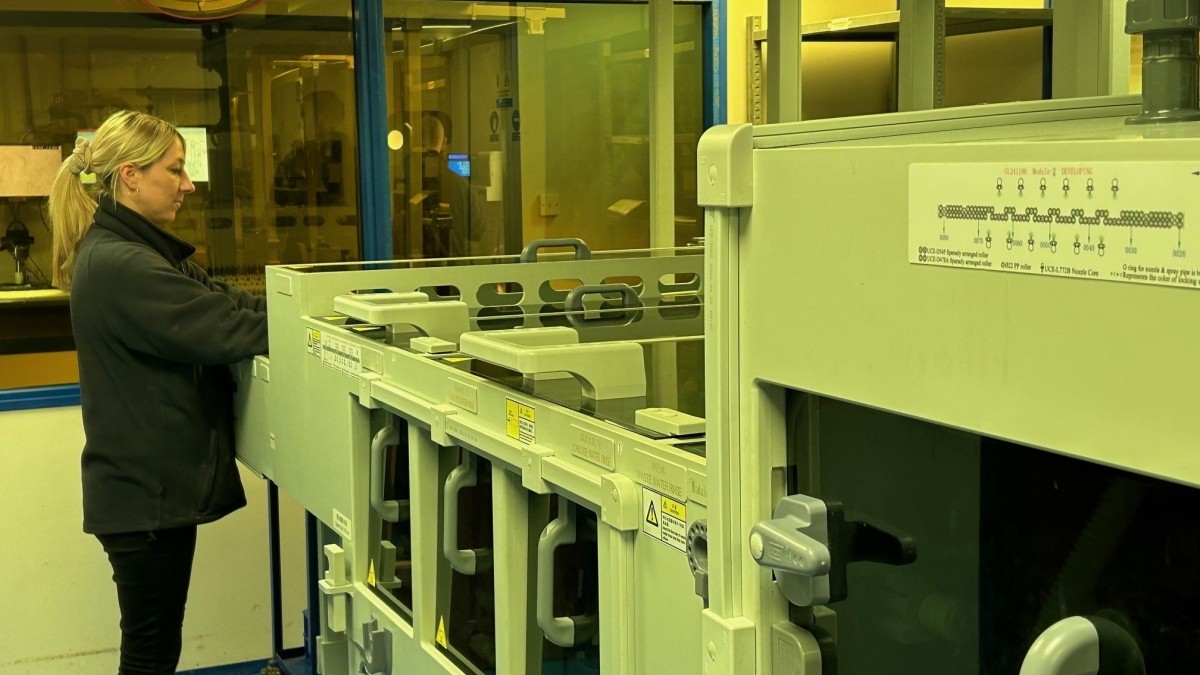
The etching step dissolves the bare or exposed metal, while the protected areas of the sheet remain largely unaffected (except for the effect of undercut as explained above). The sheet is fed into an etching machine via a conveyer that moves the sheet horizontally through the etching chamber. In the etching chamber, a set of oscillating spray nozzles deliver the etching solution to the surface of the metal where the etching reagent reacts with the metal atoms. The etching reaction is a reduction-oxidation (redox) reaction in which the metal is oxidised by the etching reagent. The oxidised metal dissolves into the solution.
The depth of the etched features produced by the reaction depends largely on the reaction time, which is controlled by setting the conveyor speed at the required value. Longer etch times (slower conveyer speeds) lead to deeper etched features. Also, longer etching times lead to increased undercut, thus requiring a larger undercut allowance when designing the photo-tool.
1.7. Stripping Of The Photoresist
After etching, the photoresist is removed in a conveyorized stripping machine by exposing the photoresist-coated sheet to a proprietary alkaline solution which weakens the adhesion of the photoresist to the metal surface, thus allowing the photoresist to be removed.
1.8. Inspection And Packaging
The etched parts are inspected individually for any defects and sample parts are measured to ensure that they meet the dimensional tolerances specified by the customer. The parts are then packed using an appropriate packaging material to avoid any damage during transport to the customer.

In short, ACE has adopted five key principles that focus on:
2.1. Photochemical Etching Reaction
Metals normally exist in a solid metallic state in which atoms are held together by a strong bond known as the metallic bond. In this state, metals are not soluble in water. To make a metal soluble in water, the atoms must be converted into positively charged ions.
When a metal atom loses one or more of its outermost electrons, it forms a positively charged ion. As a result, the atom leaves the metallic lattice and dissolves in the solution as a positive ion. The loss of electrons from an atom is called oxidation. For oxidation to take place, an oxidising agent must be present. The oxidising agent gains the outermost electrons from the metal atom and is said to be reduced.
In the etching reaction, electrons are transferred from the metal atoms to the etching reagent. The metal atoms get oxidised while the etching reagent gets reduced. The reaction is therefore a reduction-oxidation, or redox, reaction.
The basic aim of the etching reaction is to convert a metal from its solid atomic state into ions that dissolve in water. For example, iron metal is etched using ferric chloride (iron(iii) chloride). Iron atoms in the metal are represented as Fe while ferric ions (the etching reagent) are Fe3+. When an atom of iron metal is oxidised, it loses two electrons, thus forming the soluble ferrous ion Fe2+ which dissolves into the solution:
These two electrons are taken up by two ferric ions, Fe3+, from the etching solution, so that each Fe3+ ion gains one electron and is thus converted into a ferrous ion, Fe2+:
So, the overall reaction is
The rate of the etching reaction is a function of the concentration of the etching reagent, which in this case is the ferric ions. However, at very high concentrations of ferric chloride, the high viscosity of the solution can limit the rate of the reaction by slowing down the transport of ions to and from the surface of the metal. In other words, the solution becomes ‘crowded’ with ions which in turn hinders the movement of the reacting ions, slowing down the etching reaction as a result.
2.2. Etchant Regeneration
As more and more ferric ions, Fe3+, are converted into ferrous ions, Fe2+, the concentration of ferric ions decreases while the concentration of ferrous ions increases. A measure of the ratio of ferric ions to ferrous ions is the oxidation reduction potential, or ORP. As the etching reaction proceeds, this ratio decreases and so ORP decreases. To restore the oxidising power of the etching solution, the ferrous ions must be converted back into ferric ions. This is achieved by oxidising the ferrous ions using an oxidising agent known as a ‘replenisher’.
Sodium chlorate is a strong oxidising agent that is able to oxidise ferrous ions into ferric ions:
As the equation shows, this reaction requires hydrogen ions, so a strong acid such as hydrochloric acid must also be used.
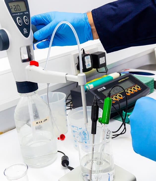
In practice, when the ORP of the etching solution falls below a target value, this triggers a dedicated control unit to add the required amounts of sodium chlorate and hydrochloric acid in order to restore the ORP.
Other regeneration methods include the use of chlorine gas or ozone and hydrochloric acid.
2.3. Hydrolysis
In addition to the etching reaction described above, ferric ions tend to undergo a spontaneous hydrolysis reaction. In this reaction, the ferric ion reacts with three water molecules in a three-step reaction ultimately forming solid ferric hydroxide Fe(OH)3. This hydrolysis reaction also produces hydrogen ions H+. A simplified version of the hydrolysis reaction is:
The formation of ferric hydroxide has two adverse effects on the etching reaction:
It is therefore important to prevent or minimise hydrolysis in the ferric chloride etching solution. This is achieved by adding hydrochloric acid. Since the hydrolysis reaction produces hydrogen ions (as shown by the chemical equation above), the addition of more hydrogen ions to the solution will reverse the hydrolysis reaction. Effectively, the addition of excess hydrochloric acid will
As can be seen, the photochemical etching process involves a number of chemical reactions. Controlling the etching process requires a good understanding of these reactions and of how they can affect the quality of the etched product.
At ACE, we combine cutting-edge chemical etching technology with decades of expertise to deliver precision metal components.
Whether you're an experienced engineer, new to metal etching, or just curious about what we do, we’ve got you covered.


 Home
Home